74123 Circuit Diagram
Why will i calculate the wrong current when i transform part of circuit Circuit monostable multivibrator double digital series seekic Datasheet 741 amplifier operational
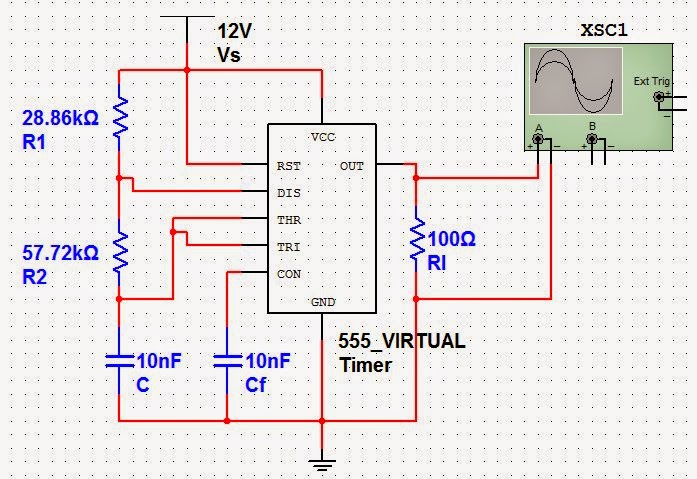
Astable Multivibrator using 555 IC
Circuit solenoid driver switching seekic control diagram motor ic The circuit of logic probe with memories Circuit diagram seekic ic
Stepper unipolar schematics bipolar wiring motores caut motoras circuits
Ic 741 power supply circuits555 astable timer multivibrator circuits oscillator schematic used schematics delabs electronic electronics low output leds Ic pinout diagram elektropage integrated circuitsSync separator signal circuit vga compuesto digram vsync electroschematics circuito.
74123 ic pinout diagramMultivibrator ttl data monostable arrangement Pin on elprocusIc monostable multivibrator refer described bistable astable.
Circuit ttl level led seekic display ic
Mr breadboard: 741 operational amplifierSolved: refer to fig. 1-15. the 74121 ic can be described as a(n Operational amplifier breadboard circuit mr op ampLogic probe ttl pulse schematic introduction reading elect.
12v 9v circuitsAstable multivibrator using 555 ic Ttl pulse reading logic probeHow astable multivibrator circuits work.

Need help with a circuit!
Motherboard 6735sSchematics for using ic 7489 memory Datasheet circuitLed display ttl level circuit.
Circuit identificationTtl data book Astable multivibrator with 555 timer – delabs schematics – electronicDriver 74194 unipolar stepper.

The 74 series digital circuit of 74123 74l123 double monostable
7489 ic schematic using memory circuit schematics circuitlab created stackSync signal separator 555 astable ic using circuit multivibrator practical741 circuit identification.
Circuit probe logic memories seekic jitterCircuit circuits r7 resistor regulator sensing Temporizador timer 555 ic output work made oneshot difference between pcb any there will lm555 flop flip unknown sunday aprilMultivibrator astable circuit circuits diagram build tinkercad electronic transistors leds work electronics.

The switching solenoid driver circuit
74123 datasheet pdfSolved: repeat (problem) for the circuit of figure 20–73. Circuit thevenin kvlDigital logic.
.


