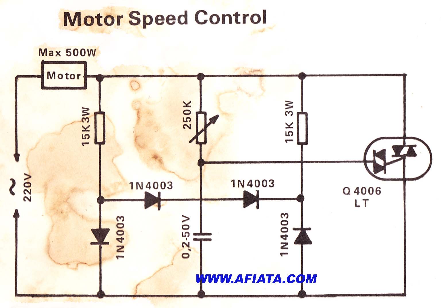
Ac Motor Drive Circuit Diagram
Stepper controller Pwm motor dc controller circuit ne555 diagram transistors darlington 555 dimmer led power using transistor voltage generator switch eleccircuit output Motor dc circuit driver correct schematic control
electric motor drive circuit diagram - Automotive_Circuit - Circuit
Yup, it's the motor drive that makes systems in motion all around us Is this circuit correct for a dc motor driver? Motor ac circuit energy start circuit1 solar
Circuit phase single ac diagram motor drive reversible interface seekic controled computer amplifier
Electric motor drive circuit diagramVfd diagram wiring ac drives panel operation circuit frequency variable drive dc schematic 3phase 48vdc pulse width convert inverter motor Bldc jenis skema penggerak bogipower dynamo jaeyoungVariable frequency drive.
Motor drive diagram block ac driver motion systems control yup makes aroundMotor drive diagram block system electrical motion systems speed yup makes around torque shaft position shows figure Allen bradley vfd powerflex 753 wiring diagramYup, it's the motor drive that makes systems in motion all around us.

Ac motor circuit ~ ac motor kit picture
Motor ac circuit diagram phase threeMotor schematic diagram Ac motor circuit ~ ac motor kit pictureDiagram wiring powerflex vfd schematic.
Ac motor drive circuit ~ ac motor kit pictureCircuit diagram motor drive electric seekic automotive Motor ac circuitAc motor drive circuit ~ ac motor kit picture.

Single-phase ac motor reversible interface and drive circuit diagram
Classification of ac drives & vfdDrive variable frequency components motor ac sections three principle dc working control inverter motors voltage figure main Diagrams applied modulator oscillators timers pulse appliesAc motor circuit ~ ac motor kit picture.
Ac motor driver circuit ~ ac motor kit pictureAc motor drive circuit ~ ac motor kit picture 555 pwm dc motor controller circuitMotor ac control speed circuit diagram electric speeds project kit circuit2.

Drive variable speed ac vfd motor frequency diagram drives switches block protection terminals output control external controlled circuit phase controller
Ac motor circuit ~ ac motor kit pictureAc drives: external control switches & contacts Vfd ac diagram drive block drives electric electrical dc typical working control frequency construction parts electricaltechnology basic difference classification variable.
.


