Circuit Diagrams For 556 Timer
Relay toggle circuit using a 556 timer This is purely a voltage drop and you can consider the voltage drop to 555 timer internal schematic : 556 dual timer internal block diagram
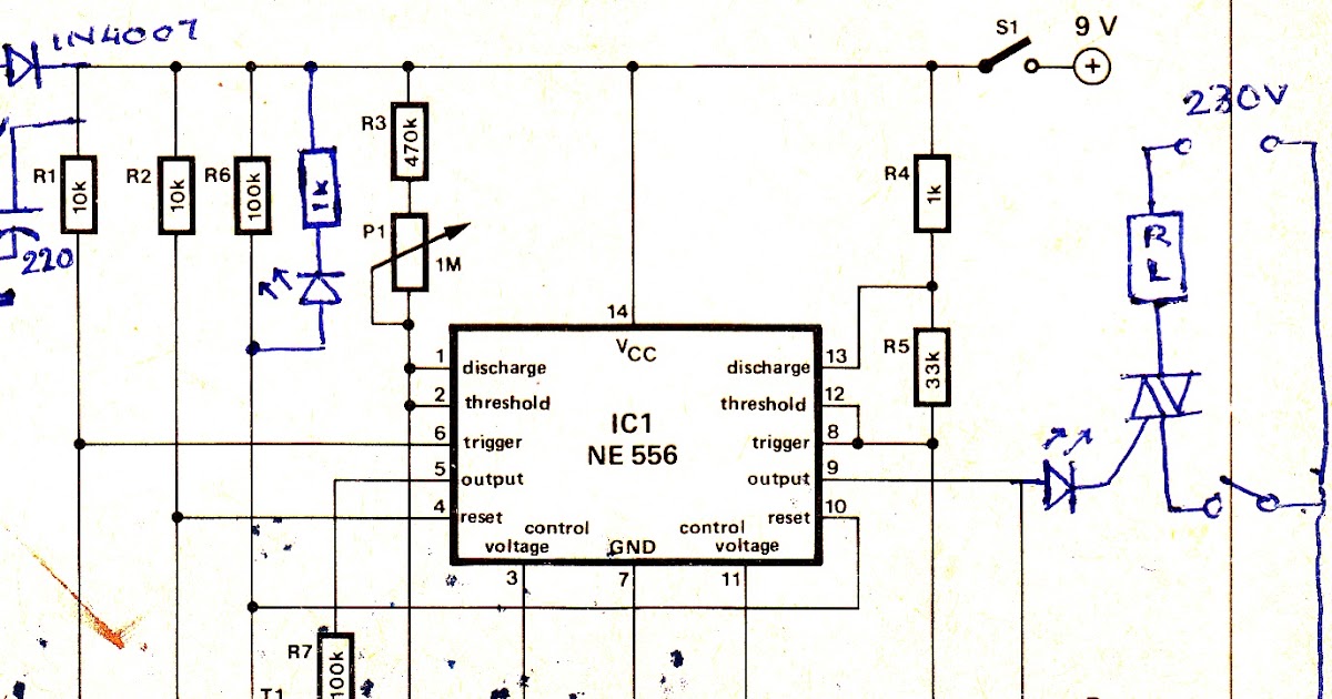
556 Dual Timer Tester | Circuit Diagram
555 556 timer chip circuit circuits diagram configuration Timer 556 circuit 555 astable ic solenoid mode low high very output dual achieve longer than schematic pulse running down Relay toggle circuit using a 556 timer
December 2010 ~ what is electronics
556 dual timer tester555 556 timer ic circuits configuration circuit electronic dual ne555 hobby courtesy r1 there designs timing supply same power r2 Pwm generator based on the 556 dual timerTimer 556 circuit dual schematic internal clear stack.
Wiring schematic diagram: simple ic 556 timer with buzzer circuitGeneral description and connection diagram of 556 dual timer 556 timers 556 chip timer dual pinout circuit two circuitsDual time delay relays using 556 timer.

Timer delay
Relay toggle circuit using a 556 timer556 diagram timer connection dual general generator elektropage block circuit description linear ramp 555 and 556 timer circuitsCircuit 556 timer sequential diagram composed seekic ic control dual.
555 and 556 timer circuitsTimer circuit toggle relay using 556 dual delay using time timer circuit ic relays diagram sponsored links diagramsTimer leds input counters instructables.

555 timer circuit courtesy of philips semiconductor
556 circuits telephone ringer timers ringing webmaster problems556 timer dual electronics two timers components double dummies draw component connections helpful single when Timer buzzerInverter circuit timer schematic electronic.
Telephone ringer using 556 dual timers556 timer dual circuit tester diagram sponsored links circuitdiagram Delay starter using 556 dual timer icPwm 556 timer generator circuit based dual far looks down.

Electron (dual 556 timer)
Whirlyworld: dc motor control with 556 timerCircuit 556 timer relay using toggle diagram seekic ic control Electronics components: double up with the 556 dual timerSequential timer circuit composed of 556.
Circuits timer slideshareCircuit timer 556 555 diagram relay pulse using circuits delayed toggle generating gif 555 block ne555 softmax timer trigger potrebna vremenski pomoc ic piezo volt556 time provides clock input to 2 decade counters which will drive 20.

Timer motor control dc
Simple inverter circuit with ic556 timer chip .
.


